As part of my journey to create an Apple CarPlay compatible infotainment system for my car project, I also wanted to use the Pi’s GPIOs to enable apps such as a backup camera. From my research, I discovered that OpenAuto doesn’t support CarPlay dongles. I chose to use Lineage OS Android, as I was able to get my CarPlay dongle to work with it. Turns out that that choice made other things like said backup camera feature quite difficult. (Its likely that OpenAuto will eventually support CarPlay dongles, but I’m on this other path now, so onward!)
A little back story
I couldn’t get CarPlay to work with OpenAuto, so I haven’t learned much about it. It looks like its pretty straight forward and well documented to get features like backup cameras working. Basically you wrap up a few Python scripts and such, and boom you have auxiliary features. I thought I’d basically do the same with Lineage OS. Wait, Lineage OS doesn’t have Python natively, no problem, I’d just have to add it. Wait, I don’t think the Python type apps will give me what I want. Ah, no problem, I’ll just cross compile Python for my Android build – how hard can that be…
I spent far too much time getting to a solution. I had a lot to learn as I haven’t done this kind of thing in a long time. It turns out that trying to cross compile Python for Android is a special punishment saved for a particular self hating masochist. (Well, at least that’s what I though – maybe someone more dialled into that sort of thing would find it ‘fun’.) As part of my painful experience, I learned quite a bit though, and distilled what my actual requirement is: I would like access to the GPIOs on the Pi. Luckily I found Lars Kellogg-Stedman’s excellent gpio-watch example of using C code to access the GPIOs .
Although I haven’t really programmed in well over a decade, at least I had a great base to get what I needed going. The programming itself is pretty basic, and my ancient background in Unix, yes Unix, made using Linux easy enough. It turns out that the cross compiling and figuring out the needed libraries would be grief enough.
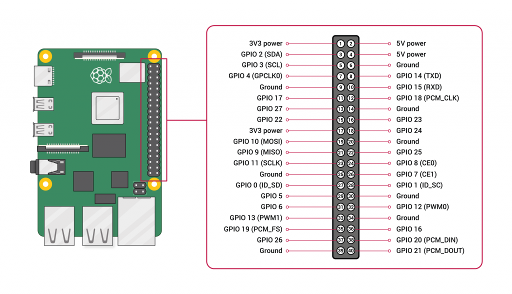
I still need to map out all the functions I plan to use Pi’s GPIOs for, but the current plan is to use the following:
- GPIO 23 (pin 16): Power up when ignition on / low power when ignition off (low: lower power mode, high: operating)
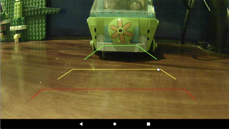
- GPIO 24 (pin 18): Back up camera (high: camera enabled)
- GPIO 25 (pin 22): Reboot, eg when system really unhappy (high: reboot)
- GPIO 16 (pin 36): Adjust backlight for day/night via headlights (low: high backlight, high: low backlight
I also need to figure out the GPIOs for a rotary encoder for a volume knob and other functions, but I’ll plan that out later. For reference, here’s the Pi’s GPIO header mapping.
What I did on a high level
On a high level, here’s what I did:
- Built a development platform
- Debugged cross compiling for Android
- Modified the gpio-watch C code
- Created GPIO script
- Added GPIO watching to the Pi’s startup sequence
Development platform
I used Ubuntu 18-04 as my development platform since I had a VMware virtual machine already installed and ready to go. To prep the machine for my Raspberry Pi 4, I installed the following tools and resources. (You may not need all of these, but I collected them iteratively and didn’t go back through to really confirm if all were needed – feel free to correct me.)
sudo apt install gcc
sudo apt install curl
sudo apt install python
sudo apt install make
sudo apt install clang
sudo apt-get update
sudo apt-get install libunwind-dev
sudo apt install gcc-multilib
sudo ln -s /usr/lib/x86_64-linux-gnu /usr/lib64
dpkg -L libunwind-dev
sudo apt install libasan4
Google’s Android NDK was used for the Android components (extracted zip through Ubuntu’s Files app):
curl -O http://dl.google.com/android/repository/android-ndk-r21b-linux-x86_64.zip
And install adb and fastboot:
sudo apt-get install android-tools-adb android-tools-fastboot
That should do it for setting up the development platform.
Debugging cross compiler
I’ve never needed to compile code for another device, so cross compiling for Android was new to me. To save my brains cells from further agony, I decided to start with a nice easy program to flush out the cross compiler:
hello.c (created in Ubuntu’s Text Editor)
/* hello.c */
#include <stdio.h>

int main() {
  printf("Hello, world\n");
  return 0;
}
It took me many iterations to figure out paths, libraries, resources, etc., but I steadily worked through countless issues. One last nagging issue was that it was looking for the asm folder, so I just coped it from the asm-generic folder – seems to work:
cp ~/android-ndk-r21b/sysroot/usr/include/asm-generic ~/android-ndk-r21b/sysroot/usr/include/asm
In the end, I found what worked for me, so I’ve documented it here in case its saves anyone else the agony I went though (feel free to optimize!) In a Ubuntu Terminal I used these commands (first update the NDK_ROOT path to match yours):
export NDK_ROOT=/path/to/android-ndk

${NDK_ROOT}/toolchains/llvm/prebuilt/linux-x86_64/bin/x86_64-linux-android29-clang \
-I ${NDK_ROOT}/sysroot/usr/include \
--sysroot=${NDK_ROOT}/sysroot \
-isystem ${NDK_ROOT}/sysroot/usr/include/arm-linux-androideabi \
--target=armv7a-linux-androideabi \
-o hello.c.o -c hello.c

${NDK_ROOT}/toolchains/llvm/prebuilt/linux-x86_64/bin/x86_64-linux-android29-clang \
--target=armv7-none-linux-androideabi \
-L ${NDK_ROOT}/sources/cxx-stl/llvm-libc++/libs/armeabi-v7a \
--sysroot ${NDK_ROOT}/platforms/android-29/arch-arm \
-pie hello.c.o -o hello
To test the exciting hello program, I then put it on the Raspberry Pi 4. I just used a USB drive to transfer files via Android File app. Temporarily, I just coped the files to the evmanic folder I created, ie /mnt/sdcard/evmanic/
I did the rest in the Android Terminal app. You’ll likely have to enable the Terminal – on Lineage OS. You’ll also want to enabled root access:
- Open Settings, and select “About tablet”
- Tap on “Build number” seven times
- Go back, and select “System” > “Advanced” > “Developer options”
- Turn on “Local terminal”
- Root access > Apps and ADB
I then copied the hello program to /data/local/tmp directory on the Raspberry Pi, as this was the first directory that I could find that would allow running executables.
Note that you’ll need to also make the hello executable (su to make you root), eg:
su
cp /mnt/sdcard/evmanic/hello /data/local/tmp
cd /data/local/tmp
chmod a+x ./hello
If you see errors like file not recognized or not executable when you run the hello program, then you have’t properly cross compiled the code for your platform, eg:
./hello
sh: ./hello: not executable: 64-but ELF file
I saw these types for message a lot! It was silly how challenging it was to get my hello world program properly cross compiled running, so I was thrilled to get that step out of the way.
GPIO C Code
OK, after all of that, I had to get the actual task done. I started with Lars Kellogg-Stedman’s gpio-watch example, as mentioned. Lar’s code is made to take command line arguments and then looks for a related script when the GPIO value changes. I updated it to create my set-gpios program that hardcodes for the GPIOs I’m looking using (in this example just GPIO 24). Below I’ve shown what I modified in main.c, and the 24 script it calls is below.
main.c (modified in Ubuntu’s Text Editor)
#define BACKUP_CAM_GPIO 24 /* Pin-18 */
#define DEFAULT_SCRIPT_DIR "/data/local/tmp"
void run_script (int pin, int value) {
  char *script_path,
       pin_str[GPIODIRLEN],
       value_str[2],
       *system_call;
  int script_path_len;
  int system_call_len;
  pid_t pid;
  int status;

  script_path_len = strlen(script_dir) + GPIODIRLEN + 2;
  script_path = (char *)malloc(script_path_len);

  // For this Android OS, need: bash
  // example: bash /data/local/tmp/24 24 0
  system_call_len = 5 + strlen(script_dir) + GPIODIRLEN + 3 + 3 + 2;
  system_call = (char *)malloc(system_call_len);

  snprintf(script_path, script_path_len, "%s/%d", script_dir, pin);

  if (! is_file(script_path)) {
    LOG_WARN("pin %d: script \"%s\" does not exist", pin, script_path);
    return;
  }

  snprintf(pin_str, GPIODIRLEN, "%d", pin);
  sprintf(value_str, "%d", value);

  LOG_INFO("pin %d: running script %s", pin, script_path);
  sprintf(system_call, "bash %s %d %d", script_path, pin, value);
  LOG_INFO("pin %d: running system call %s", pin, system_call);

  if (0 == (pid = fork())) {
    int res;
    res = system(system_call);
    if (-1 == res) exit(255);
  }

  wait(&status);

  if (WIFEXITED(status)) {
    if (0 != WEXITSTATUS(status)) {
      LOG_WARN("pin %d: event script exited with status = %d", pin, WEXITSTATUS(status));
    }
  } else if (WIFSIGNALED(status)) {
    LOG_WARN("pin %d: event script exited due to signal %d", pin, WTERMSIG(status));
  }

  free(script_path);
}
int main(int argc, char **argv) {
  struct pollfd *fdlist;
  int numfds = 0;
  int ch;
  int i;

  if (logfile) {
    int fd;
    if (-1 == (fd = open(logfile, O_WRONLY|O_CREAT|O_APPEND, 0644))) {
      LOG_ERROR("failed to open logfile %s", logfile);
      exit(1);
    }

    close(1);
    close(2);

    dup(fd);
    dup(fd);
  }

  if (! is_dir(script_dir)) {
    LOG_ERROR("error: script directory \"%s\" does not exist.", script_dir);
    exit(1);
  }

  // Manually setup GPIO pins
  num_pins = 1;
  pins = realloc(pins, sizeof(struct pin) * num_pins);

  // Backup camera
  pins[0].pin = BACKUP_CAM_GPIO;
  pins[0].edge = EDGE_BOTH;

  for (i=0; i<num_pins; i++) {
    pin_export(pins[i].pin);
    pin_set_edge(pins[i].pin, pins[i].edge);
    pin_set_direction(pins[i].pin, DIRECTION_IN);
  }

  if (detach) daemon(1, logfile ? 1: 0);
  watch_pins();
  return 0;
}
To cross compile this for the Pi, I used this makefile (again, update the NDK_ROOT path to match yours):
Makefile (created in Ubuntu Text Editor)
NDK_ROOT=/path/to/android-ndk

SRCS = main.c gpio.c fileutil.c logging.c
OBJS = $(SRCS:.c=.o)

CC = ${NDK_ROOT}/toolchains/llvm/prebuilt/linux-x86_64/bin/x86_64-linux-android29-clang \
--target=armv7a-linux-androideabi
SYSROOT = --sysroot=${NDK_ROOT}/sysroot
SYSARCH = --sysroot ${NDK_ROOT}/platforms/android-29/arch-arm
INC = -I /${NDK_ROOT}/sysroot/usr/include \
-isystem ${NDK_ROOT}/sysroot/usr/include/arm-linux-androideabi
LIBS = -L ${NDK_ROOT}/sources/cxx-stl/llvm-libc++/libs/armeabi-v7a
LDFLAGS = -pie

set-gpios : $(OBJS)
$(CC) $(SYSARCH) $(LIBS) $(LDFLAGS) $(OBJS) -o $@

main.o : main.c fileutil.h gpio.h logging.h
$(CC) $(SYSROOT) $(INC) -c main.c

fileutil.o : fileutil.c fileutil.h
$(CC) $(SYSROOT) $(INC) -c fileutil.c

gpio.o : gpio.c fileutil.h gpio.h logging.h
$(CC) $(SYSROOT) $(INC) -c gpio.c

logging.o : logging.c logging.h
$(CC) $(SYSROOT) $(INC) -c logging.c

clean:
rm -f $(OBJS)
rm -f set-gpios
After copying set-gpios to /data/local/tmp, again, you’ll need to make the set-gpios program executable (su to make your root). eg:
su
cp /mnt/sdcard/evmanic/set-gpios /data/local/tmp
cd /data/local/tmp
chmod a+x ./set-gpios
GPIO Scripts
The set-gpios code above calls scripts with two arguments. The scripts are named after the GPIO pin, eg 24, and expect two arguments. The first argument is the pin number (which I don’t do anything with), and the second argument is the GOIO pin value read by the set-gpios program.
I then wrote a GPIO script that runs commands based on the GPIO pin value. It took me a while to figure out both the actual Lineage OS commands to use and how to make these commands work. It was a ‘fun’ side journey to find out what worked on this iteration of Linux, and I finally settled on these methods below. Hopefully this will save you a lot of time. You can update the script to call an Android app (like my backupCamera example – I’ll post that in the future as well) or whatever you want.
Command to run my backup camera app (run in Android Terminal app)
am start --user 0 -n com.android.backupcamera/.CameraActivity
Command to go to Android’s home screen (run in Android Terminal app)
input keyevent KEYCODE_HOME
Here, my 24 script calls the associated action for the high or low value. The backup camera app that I wrote is initiated when GPIO 24 goes high. When it goes low, I plan to have it call the CarPlay dongle’s app, but for now I have it just going to the Android’s home screen.
24 (created in Ubuntu’s Text Editor)
#!/bin/bash
#usage: 24 <pin> <value>
#example: 24 24 0

if [[ ${2} == 1 ]]; then
  #echo "GPIO24: pin high, start cam"
  am start --user 0 -n com.android.backupcamera/.CameraActivity &
elif [[ ${2} == 0 ]]; then
  #echo "GPIO24: pin low, change to home screen, and then try starting carplay app"
  input keyevent KEYCODE_HOME &
fi
To test this, I ran set-gpios to run in the background while I played with the GPIO pin.
Command to run set-gpios in background (run in Android Terminal app)
./set-gpios &
I simply connected and disconnected GPIO 24 (header pin 18) from the 3.3V rail (eg header pin 2 or 4). With much joy the backup camera ran when when the GPIO was tied to 3.3V and the home screen when the pin was disconnected.
Startup at boot
Once I had all the pieces in place, I needed to make it all run ‘automajically’ when the system starts by calling set-gpios when the Pi boots up.
To setup things to run automatically, I created the userinit.sh script that only runs the set-gpios program in the background. This way, the set-gpios will always be running waiting for the GPIO pins to change status. I can add other tasks to this userinit script later if needed.
userinit.sh (created in Ubuntu’s Text Editor)
#!/system/bin/sh

/data/local/tmp/set-gpios &
I then copied this to /data/local and then restarted the Pi. From then on, GPIO 24 was ready for action. When GPIO 24 is tied to 3.3V, the backup camera starts and back to the home You can check out my demo on youtube.
Next steps
Not that I have a baseline GPIO monitoring program, I can go back and add the other GPIO functions.
I now need to select my actual backup camera, install it in my car, and add optoisolators that will actually trigger the GPIOs. I’ll follow with those details another time.
John
Thanks again for your really helpful set of articles, they have been really inspiring.
In case you haven’t got to this yet, my tiny contribution:
You can launch the Autokit app with
am start –user 0 -n cn.manstep.phonemirrorBox/.MainActivity
evmanic
Cool – thanks for your help!
Ximun
Can you make your app or the code for your app available? Also what camera are you using?
evmanic
Hi – yes (I’ve been meaning to, but keep getting sidetracked). I’ll try to get it posted in the next couple days… Thanks for the nudge.
Markus
Hi!
I really don’t want to rush anyone, and must apologize in advance… but as I am currently planning on building my own system, I wonder if you’ve managed to get the Pi Camera to work (pro: supports up to 10m via HDMI extension, apparently; and has wide angle options) or if you are using a USB camera (cons: doesn’t work with cables longer than 2m, apparently, unless active extensions are used).
Also, do you happen to know if your system would work with 2 cameras (front+rear)?
Can you mirror your camera feed without much latency?
How fast is the switch between the apps (rear camera back to CarPlay)?
Thank you for your blog and taking the time to share your findings with the world!
Stay safe and healthy
Markus
evmanic
Hi – I’m planning to use USB cameras, so I haven’t tried the Pi camera. I have a very, very small car, so while I may need more than 2m, it will be barely over, so I’m assuming it will work. If not, then I will be reverting and turning to the Pi camera after all! 😀
I’m also planning to add a front camera (it will likely just continually record), so I’ll update with that if/when I get it working.
The apps switch pretty slowly, so I don’t expect the cameras to come active very fast.
Thanks for your your feedback!
evmanic
As noted below, I’ve added the backup camera code in GitHub.
FilipZ
Hello!
What a great project! I’m very impressed by it. It must have taken you a lot of time to figure that stuff out so I’m very grateful for sharing all those tips for us! You have inspired me to do similar project for my own. However I’m not so good at making android applications and unfortunately this stops my build. Could you provide your BackupCamera application for the fans? 😀 We will very appreciate that.
Cheers from Poland! Your knowledge spreads worldwide! 😀
evmanic
Thanks for the feedback – I’m happy to share my journey, as so many other people’s posts have gotten me to this point. I’ve added the backup camera code in GitHub, but be warned that its a very rough draft, and I’ll update it when I get it working in my car. For what’s its worth though, here’s the link: https://github.com/evmanic/BackupCamera
Codear
Please don’t insist in slamming 5V to the GPIOs! You’ll fry the Pi. GPIO must not exceed 3,3V input voltage.
evmanic
Good catch – Thanks! I don’t remember what I used when I first set this up, but yes, it should be 3.3V. I’ve updated the post. BTW, I’m looking at using the GLOBAL_EN to wake up the Raspberry Pi, and that is 5V – I’ll post on that when I’m done with the power management aspects. Thanks again!
FilipZ
Hi again!
I’ve manage to achieve what you did here, again, great stuff! I’ looking to monitor another GPIO. After looking at the code I think What I need to do is define my next GPIO at the beggining. Then manualny set my next GPIO pin[1] and add it to my 24 scrpit in the same place where I’m echoing gpio 24. Am I right? Whats your look on that?
evmanic
Good work – not an easy task to cross-compile, etc! I think you’re on the right track. I’ve now moved to making the calls from C, as I found making the calls via shell scripts was too slow (for my volume rotary encoder). When I get a chance, I’ll follow up with an update with that info as it made sense to go all custom coding since we need to modify code to add pins anyway, but for now, here is a snippet of my code based on the method you’re using:
// Manually setup GPIO pins
// Backup camera: 1 pin
// Rotary encoder: 3 pins (A, B, button)
// Halt / shutdown: 1 pin
num_pins = 5;
pins = realloc(pins, sizeof(struct pin) * num_pins);
// Backup camera
pins[0].pin = BACKUP_CAM_GPIO;
pins[0].edge = EDGE_BOTH;
// Rotary encoder
pins[1].pin = ROTARY_A_DT_GPIO;
pins[1].edge = EDGE_BOTH; // Using Pin A will initiate the rotary encoder logic
pins[2].pin = ROTARY_B_CLK_GPIO;
pins[2].edge = EDGE_BOTH; // Recording Pin B when it changes value
pins[3].pin = ROTARY_BUT_GPIO;
pins[3].edge = EDGE_RISING; // Using the rising edge of the button
// Halt / shutdown
pins[4].pin = HALT_GPIO;
pins[4].edge = EDGE_RISING; // Using the rising edge of the signal
FilipZ
Yeah, I see. It turns out my logic was right. I did things similar to you and my previous idea , but after little more digging I’ve just added second script called 25 to use GPIO 25 on the PI. At the same time, set-gpios was watching for script 24 and 25. It turns out that everything works as expected! I’m satisfied with results as my backup camera (I’ve used Open Camera App, source code available on git) is initializing very quick and GPIO 25 is just used to make shutdown after couple seconds. With this, and somehow complicated powering system that include external powerbank, my PI and camera will work even after short lack of power! This could be helpful while parking when by incident ca stops for whatever reason, then I could quickly power car back and continue parking without losing my camera preview 😀
Ashley
So, I’ve been watching your blog here for a while as I’m working on a similar setup on my own car. The problem I’m having is that I used a USB video capture adapter and a standard automobile backup camera and none of the camera apps seem to recognize the camera.
What setup have you used? Have you found a USB backup camera, or another configuration that works?
Thank you in advance for any help.
evmanic
I’ve been using a couple generic USB backup cameras that I found on the web. Unfortunately the links for these are dead now. USB type backup cameras are surprisingly hard to find. I’ve tested out a standard Raspberry Pi camera as well (uses ribbon cable). Turns out I want one with more of a fisheye lens anyway, so I’m ordered in a Raspberry Pi cable type with fisheye. I plan to use it with ribbon to HDMI adapters so I can string a HDMI cable to back of car. I’ll update when tested.
Ashley
I figured this out.
USB video capture devices DO work, but not EVERY USB video capture device will work. Certain chipsets are ok, many are not.
For anyone else going this direction, there is an inexpensive USB video capture device made by a company called DIGITNOW on Amazon that will work with the OpenCamera app. The device I tried previous to that was never able to show an image and gave an “unable to open camera” type error. So, choose your USB video capture stick carefully…
evmanic
Great – thanks for the update!
Griffin Rudy
Hi there! I have found this page and your video after trying to make an Android/RPi carplay system of my own. I ended up down the exact same route you did and I currently have an RPi 3 running LineageOS 17.1 with an AutoKit dongle. I am looking only to run a signal from ignition to the Pi to turn the system off and on. It seems you have already solved this issue, and I was wondering if you have any advice as to how to get this to work on my system. I know very little about development for android unfortunately, but am open to any info/wisdom you may have and if you know of any other resources to look at! Cheers!
evmanic
I’ve worked out a circuit that uses an optocoupler and a ATtiny85 for the ignition (12V -> 0V) to go to a GPIO to make a call for the system to shutdown (LineageOS doesn’t support a low power standby mode). I also use a relay based on the RPi’s 3.3V to kill power to the screen’s 5V, as the screen will keep pulling some current after the RPi shuts down.
To boot the system based on the ignition (0V -> 12V), I used an optocoupler and the ATtiny85 to just invert a signal to ground the GLO_EN pin on the RPi. It’s actually more straight forward than it sounds. I’ll try to post it soon though (I have things on hold as things would change a quite a bit when convert the car to an EV).
Adriano
Thanks for your great work. I’ve used your code and I want to add other functionalities.
I’m using Rpi 3 with Lineage 16 at the moment.
I’ve found out that GPIOs are already running at boot and configurable to do some predefined tasks or buttons.
If you look in the boot partition there is a file named config.txt (/boot/config.txt).
The interesting part of that file is:
# Keys
dtoverlay=gpio-key,gpio=21,keycode=116,label=”POWER”
dtoverlay=gpio-key,gpio=20,keycode=115,label=”VOL_UP”
These keys are triggered when pulled to ground. And you can add many more functions.
Here is a list of available keys:
https://github.com/torvalds/linux/blob/v4.12/include/uapi/linux/input-event-codes.h#L64
And here you can find some documentation:
https://www.raspberrypi.com/documentation/computers/config_txt.html#gpio-control
I’m planning to try to make an app that uses i2c to comunicate with a board that gets codes from can bus ODB port. If you have suggestions, please feel free to contact me.
evmanic
Thanks for this. I briefly looked into these keys, but backed away for some reason (can’t remember why now – have to check my notes – may have done it the hard way!). Thanks again – hopefully saves others time too.
I’m also looking into CAN bus communication, but I think it will be on a separate RPi and OS. Either way, we’ll have to compare notes.
john008
can you please share all the files as i am new to this and dont know how to make android application
evmanic
If you’re not comfortable with creating an Android app, you can just call the camera app instead.
Holger Göritz
Hello,
is your system running up to now?
I am trying to do the same but on the ANDROID 12 … and I am running in big difficultys.
Thank for you advices…
Holger
evmanic
Yes, it running. I used LineageOS 16.0 (Android 9) for the RPi4, so try that to flush out the hardware, etc. I tried a later version of LineageOS but also hit issues (I think it was that there was no longer terminal access or something like that, but I’d have to check my notes). Either way, LineageOS 16.0 covers my current needs so I stopped there.
holger Göritz
Thanks for reply.
The root is the point I can’t pass up to now.
Best regards
John Manfreda
Thanks for this writeup! I am trying to make an android radio station for my Silverado. In just a day, I was able to get this guide to work for me. I do a ton of low-level embedded hardware and software work, but figuring out how I would get IO to work after installing Android on my PI seemed like a daunting task. I used a virtual machine and installed Ubuntu, and the guide was a little imperfect, but mostly worked. The biggest problem I had came down to copying code for the makefile, where I was receiving tons of errors because there weren’t tabs in the appropriate places. But, I got the GPIO24 to open an application when pressed, which is a huge accomplishment in terms of my project, and I learned how to appropriately cross-compile for the android on Pi. I hope to get some more aspects like UART working in the near future! Thank you plenty for the guide.
evmanic
Thanks for the feedback! I’m continuing to plug away. I’m currently consumed with the EV conversion (need to post on that as well)), but need to circle back on this stuff too.