My EV parts arrived, so I could finally pull the trigger and get moving on my EV conversion. Since COVID-19 had made supply chains unpredictable, I didn’t want to remove the original internal combustion engine (ICE) until I knew all the relevant EV parts were available. It was both exciting and daunting to pull Dante off the road and actually get things started.
While I had done some designing and pre-planning, until I cleared out the old engine, I couldn’t be sure of the EV component placement. The biggest pieces were the batteries, of course, so I had to make sure that space was figured out at the beginning. One major question I had to answer was if I could fit two of the Tesla batteries above the electric motor. (Spoiler alert: I can’t, but I came up with a good alternative – I think. I’ll get into that another time though.)
Removing the old engine parts
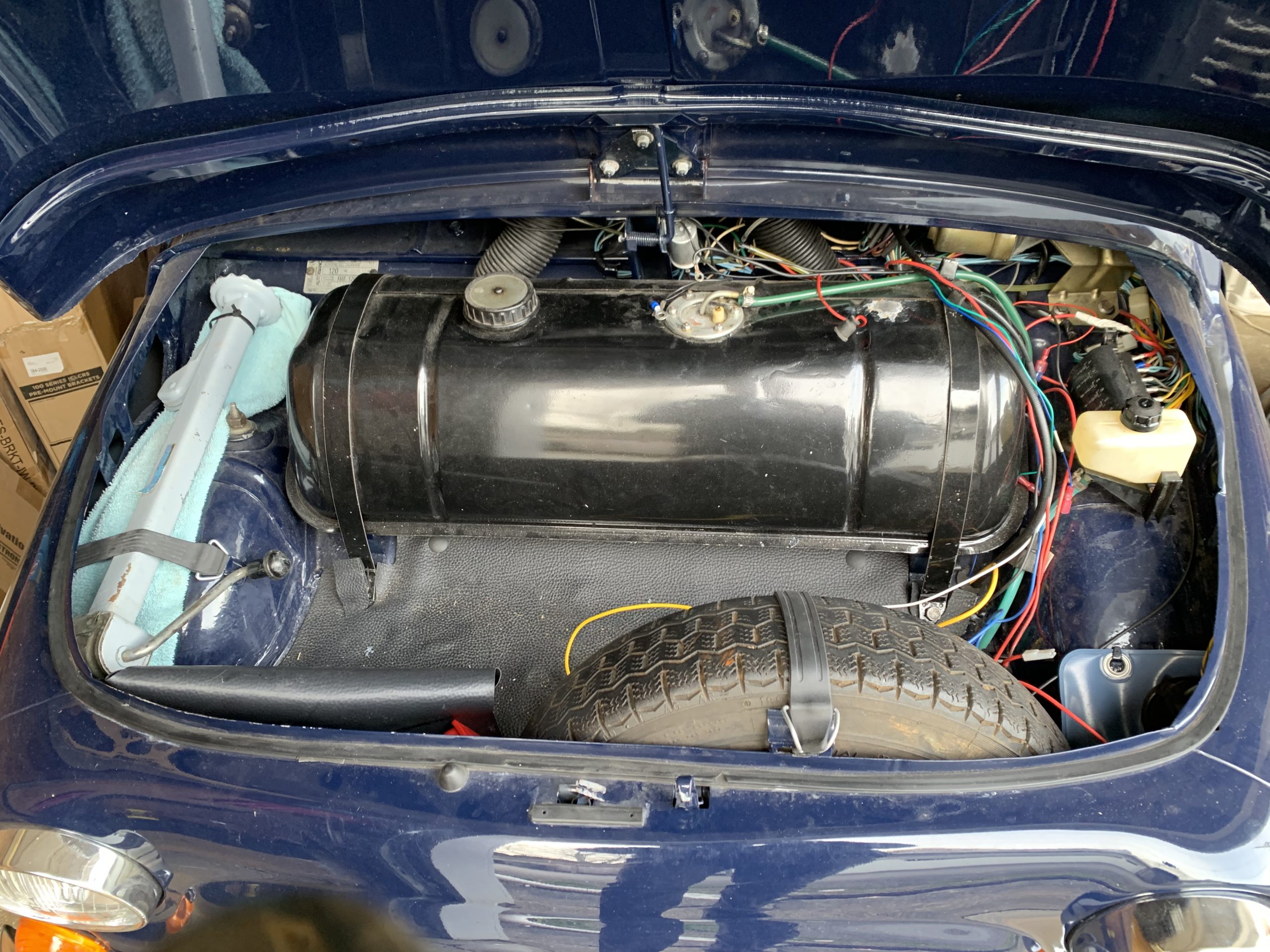
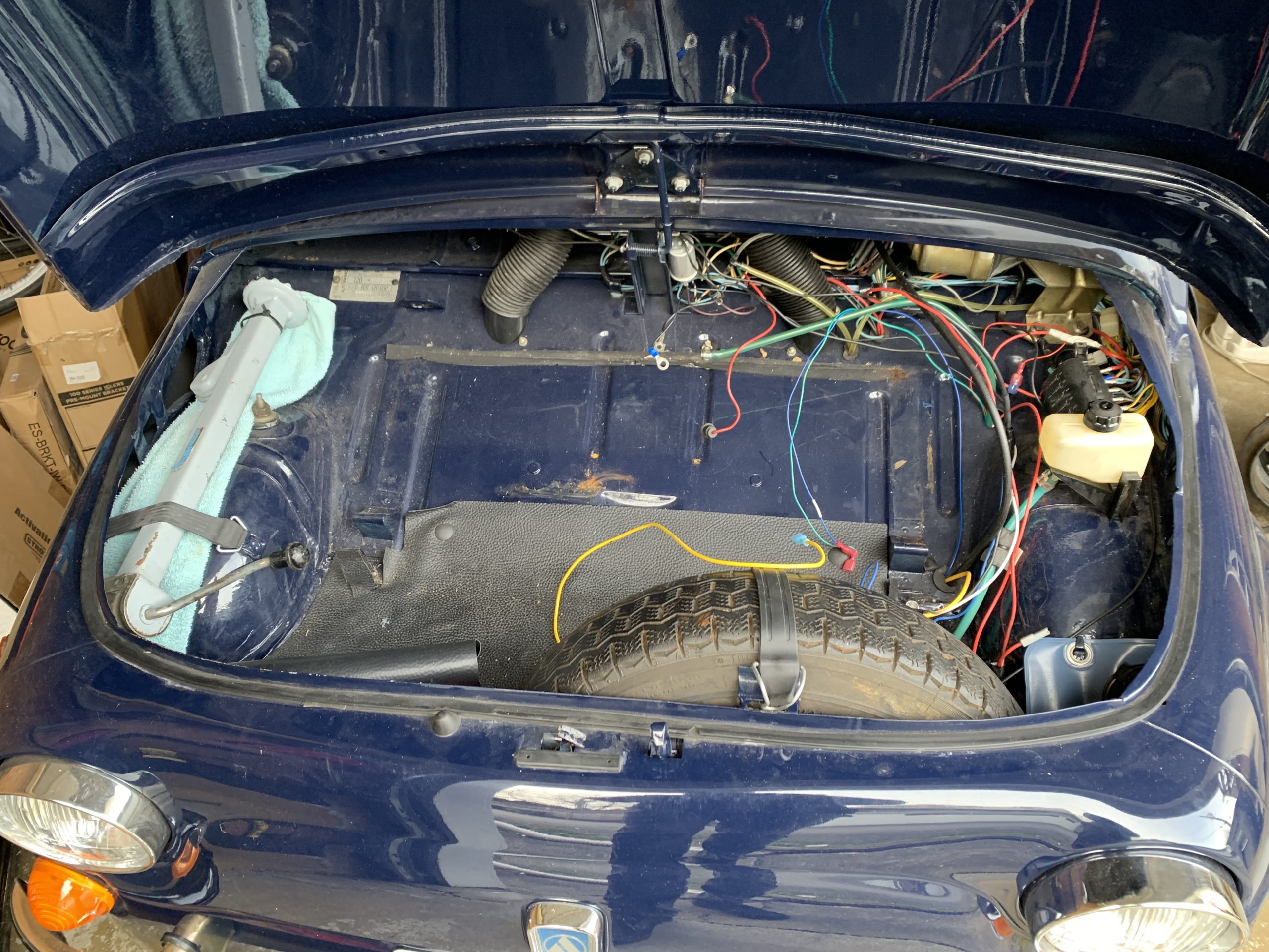
I started by draining the gas and removing the gas tank. I was finally to get a clear view of the frunk and see how much room I had for a Tesla battery. It looks like I’ll be able to place one between the wheel arches if I mount it off the floor of the frunk. I’ve seen people put a Tesla battery in the 12V battery/spare tire area of classic Fiat 500s, but I like the idea of having a spare tire (and the Tesla battery away from a possible crumple zone).
Removing the internal combustion engine was relatively straight forward. Before I did anything though, I measured the location of the bell housing from several vantage points. Since I was going to have to get a mount made for the electric motor, I wanted the new mount to get the bell housing / transaxle reasonably close to the original height. When I felt I had that documented, I started the real work.
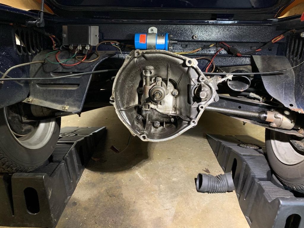
I started by rolling the rear of car onto a couple of ramps. Then I pulled off the lower rear panel. This is a great feature of the classic Fiat 500 family that gives a lot of room to work, considering the small size of the car. (Its likely they had to do it that way, otherwise the car couldn’t be assembled or serviced!)
I then detached all the engine wiring, gas line, clutch cable, choke cable, starter cable, etc. Next I removed the starter motor to get that out of the way. Since the engine is so small and light, I used a small transmission jack to support it. I removed the old engine support and the rest of the bell housing bolts. It took a bit of effort due to the angle of the car (and engine) sitting on the ramps, but I was able to pull the engine off the transmission axle and out of the engine compartment.
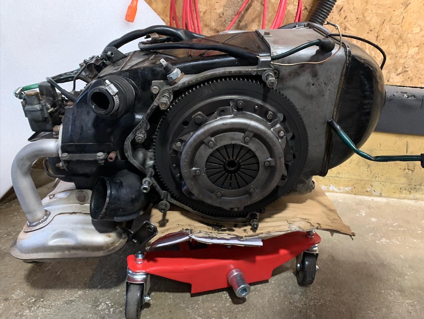
Figuring out the motor coupler
My plan for this conversion is to keep the car’s clutch and transmission / transaxle, so the next task was to design the bell housing adapter plate and motor coupler. The bell housing adapter physically connects the electric motor to the bell housing, and the motor coupler allows the electric motor shaft to drive the original flywheel. The flywheel will then connect to the original clutch assembly as before to the transmission / transaxle. The transmission will work as it did originally. (That said, I can likely just leave it in one gear since the electric motor offers considerably more torque.)
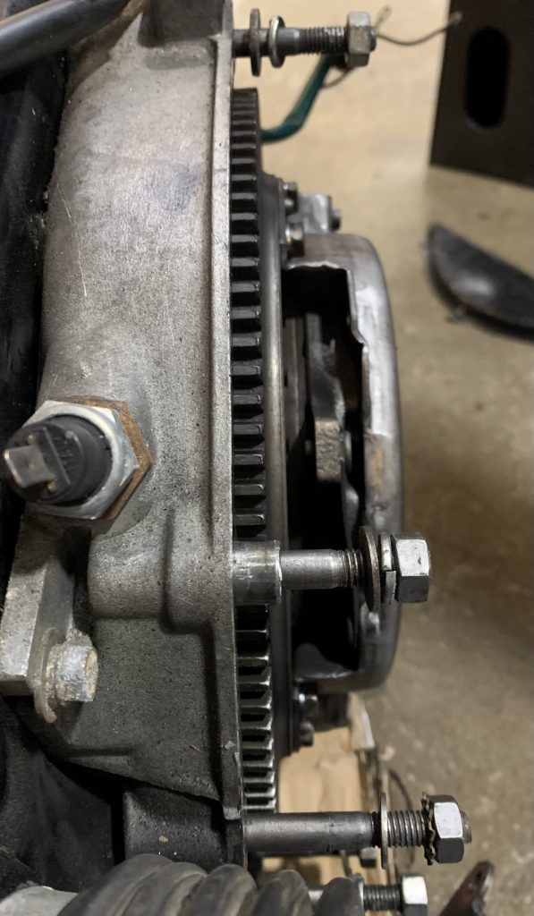
To accomplish this new design, a critical piece is to have the flywheel sit the same in the bell housing as it did with the old engine. Not only does it have to be centred, it needs to be at the same depth. Before removing the flywheel from the old engine, I took precise measurements to understand how much of the flywheel needs to be within my bell housing adapter design and the bell housing itself.
So now I had to design the adapter plate and coupler to meet this spec – not an easy task. First I had to figure out the length of the motor coupler. This was a combination of meeting the flywheel placement requirement while working with the motor’s shaft length. I should note that the HPEVS AC-20’s shaft has a 3/16” keyway to make the mechanical connection to whatever you’re driving. In my case, this will be my coupler.
I could have cut down the electric motor’s shaft. There was an engine mount that was intruding into the new electric motor’s space, so cutting down the shaft would help give clearance. I did some rough torque load calculations to figure at what length the key in the shaft would fail. While the torque failure calculations suggested I had multiple factors of safety, I’m not a mechanical engineer so I don’t have a good sense of what’s a good rule of thumb, etc. That, and I wasn’t comfortable cutting the shaft down to the very short length necessary to have the new motor clear the original rear engine mount anyway. I left the electric motor shaft length as is. In the end this also required more aluminum for the mounting plate, but I’ll get to that below.
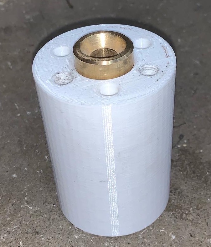
I actually over simplified details above. Another consideration was that the transaxle actually extended into and past the flywheel into the engine, or now in my case the motor coupler. While my coupler could have accepted the axle directly, I decided to use an original bushing so I didn’t have to think about replicating it’s shape in the coupler design or worry about the metal properties of the coupler material. The bushing protruded from the old engine, so that would have to be taken into account as well.
I had the specifications I had to meet: flywheel placement, shaft length, and transaxle mating depth. From my measurements on the original engine, I determined the depth of flywheel starter teeth were in the bell housing. This is what I had to duplicate with my design. To do this, I had to figure out the distance from the bell housing side of the starter teeth to the opposite side mounting surface. (While the flywheel looks kind of like a flat plate, its profile is a bit more complicated.)
After some measurements and math, I determined the distance from the bell housing side of the teeth to the motor side mounting surface. In the end I got the coupler length dialled in to meet these needs. I designed the coupler in CAD, and 3D printed prototypes in white PLA plastic. My prototype was handy for my mock ups and testing with the adapter plate prototype (see below).
Designing the bell housing adapter plate
The bell housing adapter plate was much more involved. The AC-20 electric motor side was straight forward, since I had the luxury of a mechanical drawing from HPEVS showing the mounting bolt locations. The bell housing side took a lot of trial and error though. I started with many measurements for initial locations of the bell housing mounting bolts and transaxle drive shaft. I also measured to create a basic overall shape of the adapter itself. I created the initial design in CAD, and then printed out a minimal template with the 3D printer. For the templates, I cut out has much material as possible to save time and to minimize PLA plastic waste. I did have to keep it thick and a sturdy enough shape though, as I needed it rigid enough to check hole placement accurately. I had to go through many of these templates to get it right. The axle had to be exactly centred, otherwise things will wear far too quickly. Not to mention that there would be considerable vibration from the motor. This required all the bolt hole locations to be very accurate.
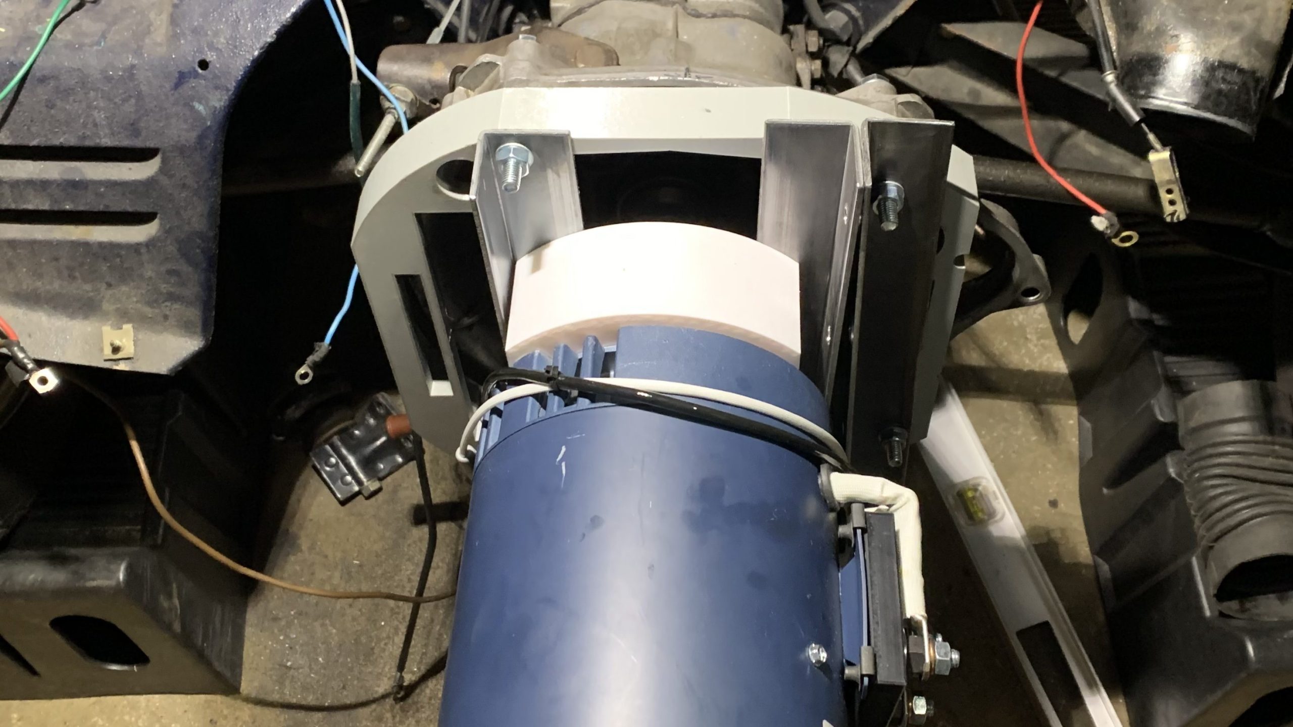
Once I had this physical attachment to the bell housing figured out, I needed to take into account of the depth of the rest of the flywheel so it spins freely in the adapter plate. My original design would have required a sizeable (and expensive) chunk of aluminum billet, so I decided to split into two pieces: the bell housing adapter piece and spacer. I 3D printed prototypes of these as well, to check on the car. (I temporarily added some angle iron, as the 3D printed plastic wasn’t strong enough to support the weight of the electric motor on its own.)
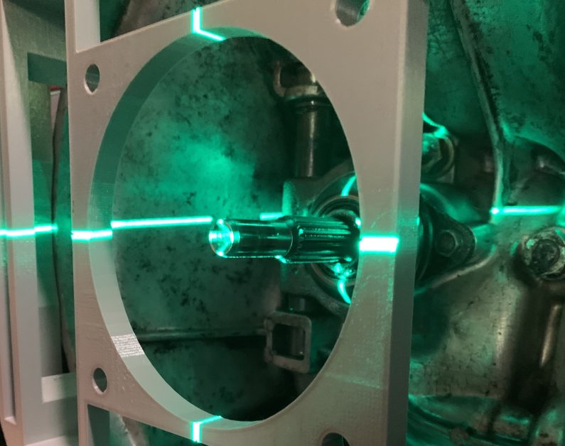
Testing the prototypes
I bolted these pieces onto the AC-20, slid the coupler prototype on and attached the flywheel. I checked the protruding depth of the starter teeth and it looked good. I then lifted it into place with the transmission jack. It fit well, so I pulled it apart to check with a laser for alignment to centre on the transaxle shaft. I was happy with that as well, so I started to get quotes for CNC manufacture.
When I raised the AC-20 motor into the right height for original bell housing placement, it was clear that I needed to cut off the original engine mounting point to make room. After a cathartic angle grinder session, the old engine mount was cut off. So far this is the only ‘destructive’ thing I’ve done to the car. Not a big deal since I’ll keep my car electric, but it was against my original plan of making the conversion easily reversed. Worst case though, the old engine mount can always be welded back on.
Next up I’m working on the electric motor mount and the battery boxes while waiting on the CNC adapter plate pieces. This is getting fun!